Hyper Pro Voltra Mount
A flat steel plate that attaches a Voltra DIY Dock to the Hyper Pro crossmember, for loaded back extensions.
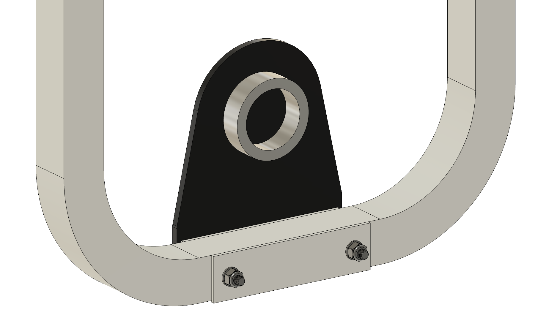
Black: the plate, your download (200.0 × 242.5 × 7.9 mm). Gray: the foot, dock and hardware, for reference. The bends and leg length of the foot are approximate.
Price and file
Plate price · RMFG · powder coated
- 1 plate
- $54.20
- 2 plates
- $42.88 each
- 4 plates
- $38.19 each
- 6 plates
- $36.33 each
- 12 plates
- $33.37 each
Quote from 5 Oct 2026, before tax. Ground shipping from RMFG is free. Get a new quote when you order. Hardware: $3.91 for the parts used, $32.82 for full packs.
The plate only, in millimeters. Before you order the plate, measure your machine. Then upload this file to RMFG.
Make it
- Measure your machine.
The Hyper Pro has many versions, and the versions do not have different names. Before you order the plate, do the four checks below at the bolted joint. Do not loosen the bolts.
You need a 17 mm wrench, a tape measure, a steel ruler and calipers.
The joint is at the center of the U-shaped foot. The bolt heads are on the front plate, and the nuts are on the rear plate. The front plate has two long edges: the U-side edge, toward the inside of the U, and the tube-side edge, at the center tube. -
1. Bolts
Count the bolts in the joint. Put the 17 mm wrench on each bolt head. If the wrench is loose, measure across two opposite flats of the head with the calipers.
Pass: two bolts, with 17 mm heads (the wrench fits with no play) or 16 mm heads. Both sizes are M10.
-
2. Distance between the bolts
Use the tape measure. Measure at the sides of the bolt heads, above the washers.
- A
- From the outer side of one bolt head to the outer side of the other bolt head. Hook the tape on one head. Lay it across the tops of the two heads.
- B
- From the inner side of one bolt head to the inner side of the other bolt head. Push the end of the tape against one head, above its washer.
Add A and B. Divide the result by 2. This gives the distance between the bolt centers.
Pass: 149 to 151 mm. A is approximately 166 to 170 mm, and B is approximately 130 to 134 mm.
-
3. Height of the front plate
Use the steel ruler. Put it flat on the front plate, between the center tube and a bolt. Hold it at 90° to the long edges.
- C
- From the tube-side edge to the U-side edge.
Pass: 49 to 51 mm.
-
4. Thickness of the joint
Use the calipers at the U-side edge, beside a bolt. Put one jaw on the front plate and one jaw on the rear plate. Keep the jaws off the bolt heads, the washers and the nuts.
- D
- From the outer face of the front plate to the outer face of the rear plate.
Pass: 52 to 63 mm. If D is more than 60 mm, use M10 × 90 mm bolts (McMaster 91280A656) in place of the 85 mm bolts in the parts list.
If a check does not pass, do not order the plate.
-
- Order the plate from RMFG. Upload the STEP file at rmfg.com. Select Steel, Hot Rolled, 0.313 in, and Deburring. Select a powder coat in the color that you want. The plate is flat, with no bends or welds.
- Get the dock and the mounting hardware. Use a Beyond Power DIY Dock with its eight M4 × 16 screws and its magnetic pad. Get the M10 hardware in this list.
| Part | Quantity | McMaster | Pack price |
|---|---|---|---|
| M10×1.5×85 mm hex bolt, class 8.8, zinc plated | 2 | 91280A177 | $13.56 / 10 |
| M10 flat washer, Ø20 mm, zinc plated | 4 | 91455A140 | $8.62 / 100 |
| M10×1.5 nylon locknut, class 8, full height | 2 | 97131A150 | $10.64 / 25 |
McMaster prices from 22 Oct 2026. One plate and its hardware: $58.11 (parts used) or $87.02 (full packs), before tax and McMaster shipping. The dock and the Voltra are not included.
Tools: a tape measure, a steel ruler and calipers to measure the joint, a hex key or torque driver for the dock screws, and two 17 mm wrenches or sockets.
Use it
- Attach the dock to the plate. Do this on a bench. Put all eight M4 screws through the plate from the rear. Do not tighten a screw until all eight screws are in position. Tighten the screws in a cross pattern to 2–2.5 N·m. Put the magnetic pad in the center of the ring. Refer to Beyond Power’s DIY Dock installation instructions.
-
Attach the plate to the joint. Support the machine so that there is no load on the joint. Then remove the two bolts from the joint. Put the plate on the joint, as the picture shows. Install the new M10 bolts with a flat washer under each bolt head and each nut.
Installed on the joint at the center of the U-shaped foot. - Tighten the nuts. Hold each bolt head and tighten its locknut firmly. Make sure that the plate is flat on the joint. Make sure that the bolt thread goes fully through the nylon of each locknut.
To remove: remove the Voltra from the dock. Hold the plate. Hold each bolt head and remove its locknut. Then remove the bolts and the plate. Install the original bolts.
Technical details
Fit
- Freak Athlete Hyper Pro: two M10 bolts on 150 mm centers. The joint is a 51 mm crossmember between two 4.3 mm plates, 59.6 mm thick before you add the plate and washers. The bolts are approximately 25 mm from the U-side edge of the 50 mm front plate. These dimensions are measured on one machine.
- Bolt length: the 85 mm bolts extend 0.5–2.4 mm past the locknut.
- 3D view: the widths and depth of the U-foot are measured: 17¾ in inside, 21⁹⁄₁₆ in outside. Its bend shape and leg length are approximate. The view does not show the tube walls or the remaining parts of the machine.
Dimensions and specifications
- Part
- HP1-1-R3Design HP1, part 1, revision 3
- Revision date
- 5 Oct 2026
- Status
- Built and tested
- Material
- Hot-rolled steel, 5/16 inRMFG’s 0.313 in (7.94 mm) plate. The calculations use A36: minimum yield 248 MPa (36 ksi).
- Finish
- Deburred, then powder coatedAny color. RMFG applies it.
- Size
- 200.0 × 242.5 × 7.94 mmWidth × height × thickness
- Mass
- Approximately 2.47 kgSteel at 7.85 g/cm³, without the powder coat
- Bends
- NoneFlat plate
- Bolt holes
- Two, 11 mm150 mm apart, for M10 bolts
- Dock holes
- Eight, 4.7 mmThe DIY Dock M4 pattern
- Dock position
- 75 mm clearFrom the crossmember edge to the nearest edge of the dock
- Outline
- R76 crown, four R12 cornersThe crown is centered on the dock center.
- Hardware to buy
- Two M10 bolts, four washers, two locknutsMcMaster-Carr 91280A177, 91455A140 and 97131A150
- Tolerances
- The fabricator’s standardCut to the STEP file. All holes are clearance holes.
Dimensions in millimeters. The views and dimensions are from the fabrication STEP, and the mass is from the Fusion model. Heights on the dock face are from its base edge (0). Dashed gray lines show the Hyper Pro joint and the DIY Dock for reference. REF marks a reference dimension.
Load calculations
Yield is the stress at which steel starts to change shape permanently. Minimum yield is A36’s specified lower limit. Expected strength is the higher yield value assumed in these calculations.
All values in this section are from calculations. 250 lbf is the maximum in the Voltra’s weight modes, with Overdrive. 400 lbf is the maximum in its Isometric Testing mode. The model uses 7.68 mm steel, the minimum thickness of 5/16 in stock. The load is 127 mm from the dock face. The 250 lbf and 400 lbf loads include an additional 8 kg in the same direction. The table shows the maximum movement at the load point, with the plate rotation. It does not include movement in the Voltra or the machine.
| Load | Steel | Movement under load | After unloading |
|---|---|---|---|
| 250 lbf training | A36 minimum | 1.901 mm | Not calculated |
| 400 lbf Isometric Testing maximum | A36 minimum | 2.963 mm | 0.0041 mm |
| 982 lbf adapted overload | A36 expected strength | 7.064 mm | 0.147 mm |
| 982 lbf, one direction | A36 minimum | 8.734 mm | 1.768 mm |
The 250 lbf and 400 lbf sequence and the expected-strength overload each use five directions. Each value is the maximum from the five directions. The minimum-strength overload uses one direction, the direction with the most movement. Expected-strength A36 uses 323 MPa yield, 480 MPa ultimate strength and strain hardening to 15% uniform strain. These values are assumptions, not values from a material certificate.
The elastic calculation at 400 lbf uses 21 directions. At the washer edge, the coarse mesh gives 309.1 MPa. Two finer meshes give 238.0 MPa and 230.5 MPa, less than the 248 MPa minimum yield of A36. With contact stiffness ten times larger, the first fine mesh gives 237.5 MPa. The margin is small, and the local stress changes with the mesh.
The nonlinear model shows no plastic strain at 250 lbf, except in narrow bands at the ideal edges. At 400 lbf, the plastic strain is 0.0028%. The 982 lbf (4,366 N) overload is adapted from a formula in ISO 20957‑2 for equipment with external loads. With expected-strength A36, the permanent movement at the load point is 0.147 mm. With minimum-strength A36, it is 1.768 mm.
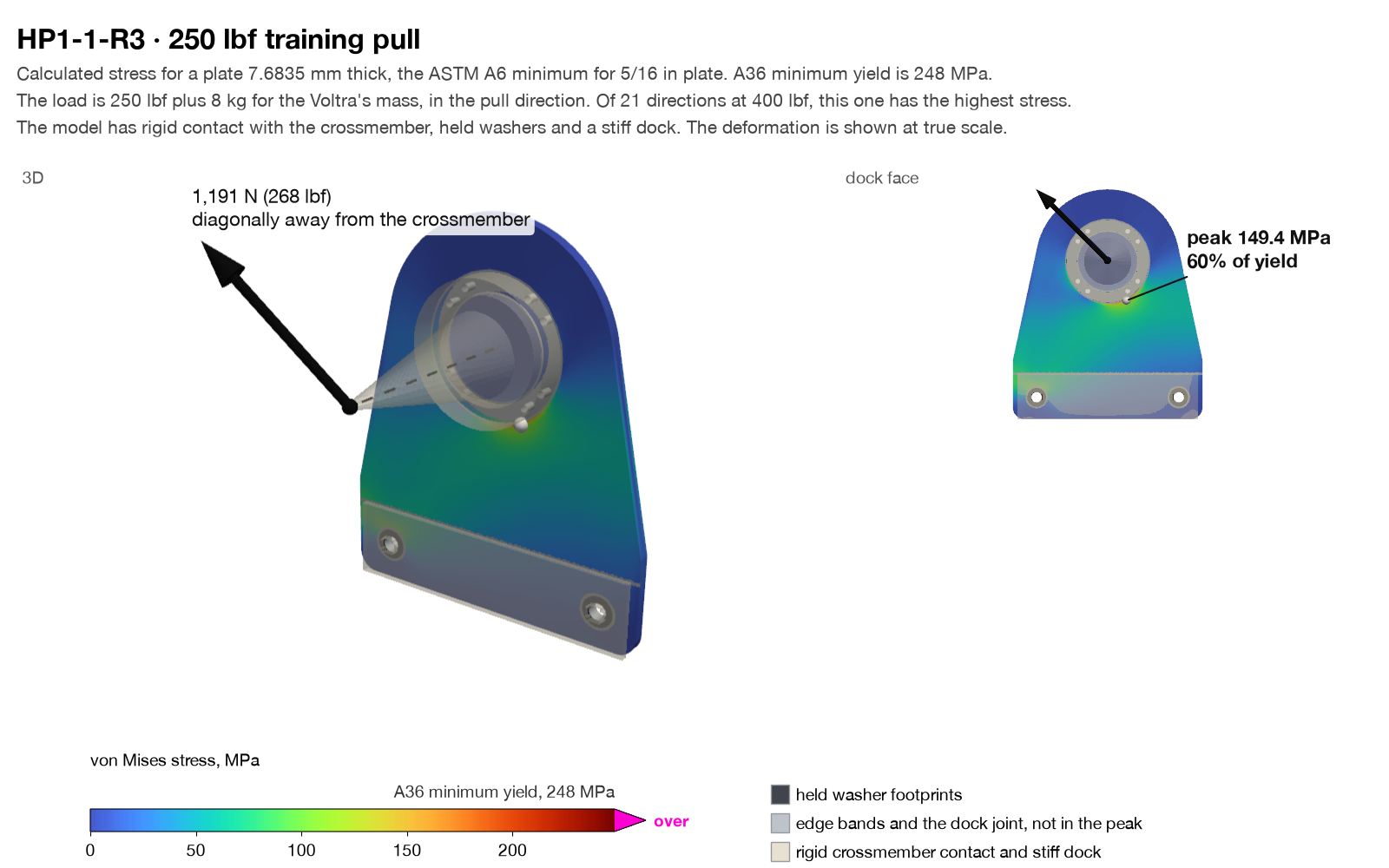
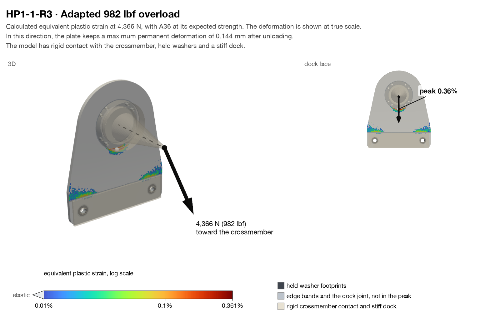
The model includes contact with the existing joint plate, and fixed areas under the washers. The maximum clamp force necessary at each bolt is approximately 8.82 kN at 400 lbf and 20.25 kN at the overload. These are calculated demands, not the bolt preload. The U-foot in the 3D view is for reference only. The model does not include the tube walls, welds, dock screws, slip or the full machine.
Files and revisions
- HP1-1-R3 · fabrication STEPFlat plate, millimeters · 34 KBSHA-256 28a0bdf633fb3c91b5c027e09c96efc318732ebede42ffb7f18f483c3d26d3a4
- HP1-1-R3 · viewer mesh
R3 · 5 Oct 2026 · First shared revision.